Pipe Flange
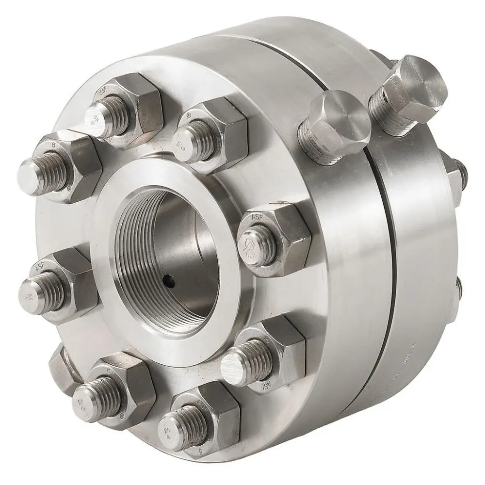
Pipe Flange
Commonly installed on metering loops in refineries, chemical plants and power stations for flow instrumentation.
Product details
A matched flange set (usually WN or SO base) with two pressure tapping holes. An orifice plate is clamped between the pair. Differential pressure from tapping holes is measured to calculate flow rate.
An orifice flange is supplied as a matched flange set, normally based on a WN or SO flange. Two pressure tapping holes are arranged in the pair so that the differential pressure across the clamped orifice plate can be read.
The orifice plate is not part of the flange ring itself: it is clamped between the two flanges of the pair, which holds the plate in position in the line while the taps stay open to the flowing medium.
The pair works as a small measuring assembly. The three steps below describe how the clamped plate and the two tapping holes turn a pressure difference into a flow rate.
An orifice plate is clamped between the pair. The two flanges of the matched set hold the plate in position in the line, so the plate sits directly in the flow path.
A matched flange set (usually WN or SO base) with two pressure tapping holes. Each tapping hole leads the pressure on its side of the plate out of the line to the measuring instrument.
Differential pressure from tapping holes is measured to calculate flow rate. The difference between the two tapped pressures is the signal used by the orifice plate flow meter.
Note: the flow rate is calculated from the differential pressure measured at the two tapping holes of the matched pair, so the flange pair and the orifice plate are used together.
Orifice flanges are available with the following faces:
Inline flow measurement in oil, gas, chemical, water treatment, used with orifice plate flow meter.
| Standard system | Standards |
|---|---|
| ASME | ASME B16.36, ASME B16.5 |
| EN | EN1092-1 |
| GB | HG/T 20615 |