
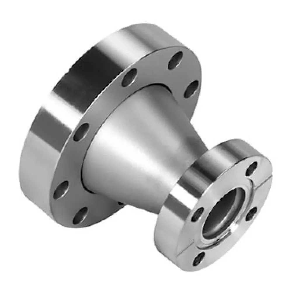
Pipe Flange
Reducing Flange
Used in compact piping layouts for equipment nozzles, pump and valve connections where pipe size transition is required.
- Category
- Pipe Flange
- Specification
- RF / ASME B16.5 / reducing bore
- Product code
- RED-RF
Product details
A reducing flange is an integrated flange that carries different nominal sizes on a single component: the flange face is one size, while the central bore reduces to a smaller pipe size.
Two ways to make a size change at a flanged joint
When a pipeline has to step from one pipe size down to another at a flanged connection point, the conventional arrangement puts two items in series — a flange of the larger size, plus a separate reducer fitting that carries the transition into the smaller bore.
A reducing flange takes the other route. It combines flange + reducer into one component, saving a separate reducer fitting. The size transition lives inside the flange body itself, so the joint is completed with one item instead of a flange and a reducer stacked together.
| Arrangement | Separate flange + reducer fitting | Integrated reducing flange |
|---|---|---|
| Parts at the joint | Flange of one size and a separate reducer fitting | Flange and reducer combined into one component |
| Size transition | Reduced by the separate fitting | Central bore reduces the flange face size to the smaller pipe size |
| Fit | Extra item to source and install at the joint | Saves a separate reducer fitting; suits limited space layout |
What the two approaches differ on
Read side by side, the differences sit in space and in process rather than in any single performance figure:
- Space — the separate route occupies the room of both a flange and a reducer fitting; the integrated flange answers piping transitions in limited space layout.
- Process — the separate route adds a part to source, handle and install; the integrated flange combines flange + reducer into one component and saves a separate reducer fitting.
- Where the transition sits — with a separate fitting the size change happens beyond the flange; with a reducing flange it happens within the flange, between the flange face size and the smaller bore.
Where a reducing flange is used
It is chosen for piping transitions between two different pipe sizes at flanged connection points, for limited space layout, for instrument take-off, and for pump or nozzle size changes. In each of these the point of the part is the same: a size step is needed right at the flanged joint, and one component is preferred over two.
When it is not recommended
It is not recommended for extreme high pressure critical service. Where the duty is critical and the pressure very high, the integrated size transition at the flange is not the arrangement to reach for.
Available faces and applicable standards
Available faces: RF, FF, RTJ, MFM, T&G.
| Standard body | Applicable standards |
|---|---|
| ASME | ASME B16.5, ASME B16.47 |
| EN | EN 1092-1 |
| GB | GB/T9112 |